Prototype Development and Motion Analysis of Lightweight CT Gantry Frame
Background and Motivation
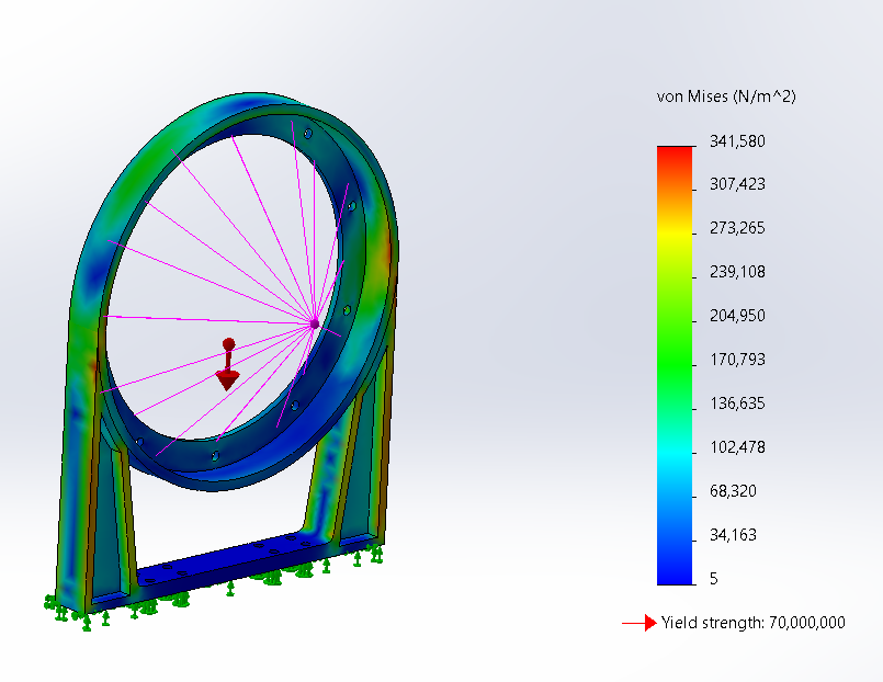
In the previous research on Redesigning a CT Scanner, the study demonstrated that the aluminium alloy used in conventional CT gantries could be replaced with Carbon Nanotube (CNT)-reinforced Magnesium alloy (AZ91D-CNT) to significantly improve the strength-to-weight ratio. That work focused primarily on a direct modelling approach and finite-element analysis of the gantry’s structure.
This continuation reflects both my curiosity and my personal drive as a mechanical engineer to transform analytical design into a real, working system.
The objectives of this prototype phase can be summarized under three key aspects:
Visualization and Communication: To transform the digital model into a tangible structure demonstrating geometry, rotation, and assembly for academic and professional presentation.
Mechanical Validation: To verify smooth rotation, gear alignment, and bearing performance under real conditions.
Hands-on Learning: To gain practical understanding of torque, motion transmission, and dynamic stability, complementing the analytical insights from Previous design.
Design Overview
SolidWorks Scaled Model
A 1 : 10 scaled CAD model of the optimised gantry was developed in SolidWorks using a parametric modelling approach.
Key design adaptations included:
Integration of gear teeth on the outer periphery of the rotating ring.
Addition of a motor mount and base frame compatible with a small DC motor.
Design of bearing housings for cylindrical roller bearings to support smooth rotation.
Simplification of non-critical features to suit FDM 3D-printing tolerances while maintaining geometric accuracy.
The final assembly comprised a stationary frame, rotating ring, spur-gear drive pair, and bearing supports, connected using M3 bolts.
Prototype Fabrication
3D Printing
Printer: Desktop FDM printer (180 × 180 × 180 mm build volume).
Material: PLA filament, 0.2 mm layer height, 40 % infill.
Orientation: Vertical printing of the ring for concentric accuracy.
Post-processing: Reaming of bearing bores and light filing for gear engagement.
Assembly
Cylindrical roller bearings (Ø 12 mm × 3 mm) were fitted for low-friction rotation.
A 6 V DC motor was mounted on the base and coupled via a spur-gear pair
All components were aligned and fastened using M3 bolts and spacers.
Simulation and Analysis
Bearing Design
Bearings were modelled in SolidWorks with standard geometry (Ø 22 mm × Ø 8 mm × 7 mm).
They were constrained to the fixed frame while allowing free rotation of the ring.
SolidWorks Motion Simulation
A motion-study simulation was conducted to evaluate the angular velocity and displacement of the rotating ring.
The analysis confirmed smooth, uniform motion, accurate gear engagement, and stable rotational behaviour without excessive vibration or backlash.
Motor Torque Calculations
The total resisting moment from gravity and friction was estimated to be approximately 0.35 N·m.
Considering the 1:5 gear ratio, the required drive torque at the motor shaft was calculated to be about 0.07 N·m.
A 6 V DC motor rated at 0.08 N·m torque and 0.2 A current was selected, which achieved steady rotation at approximately 60 rpm, consistent with the simulation results.
Observations
The printed frame maintained rigidity with minimal deformation.
Bearings ensured smooth, low-friction rotation.
Torque readings from simulation aligned closely with experimental data.
The prototype effectively demonstrated the rotational concept of a CT gantry.
Discussion
This stage bridged computational modelling and real-world mechanical validation.
3D printing proved invaluable for verifying assembly tolerances and gear function quickly and affordably.
Though PLA is less stiff than Mg-CNT alloys, the scaled prototype replicated the key dynamic behaviour and validated the concept’s mechanical feasibility.
Conclusion
A functional 3D-printed prototype of the lightweight CT gantry was successfully designed, fabricated, and tested.
Through SolidWorks modelling, motion simulation, and motor-torque validation, the study confirmed:
Smooth gear-driven rotation,
Accurate bearing alignment, and
Practical feasibility of the redesigned gantry concept.